Construction Details - Aerofoil
System Description
Wing-shaped panel elements, or fins, combine optimum solar effectiveness
with a firm and futuristic appearance.
- Aluminium extruded wing-shaped profiles
-
6 different standard profiles from 200 to 450 mm wide
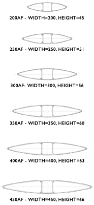
- Fins fixed at a chosen angle between 0 and 180 degrees in increments of 5 degrees
- Adjustable fins with motorised operation, suitable for Building Management Systems
-
V-bracket fixtures, available in 0, 30 and 45 degrees for the
200 - 300AF -
Cup bracket fixtures, available in 0, 30 and 45 degrees for the
350 - 450AF - Two standard supporting structures are available, tube or flat bar
- Corner solutions are available for fixed systems
- Available anodised, in polyester or PVDF coating (RAL) or in wood tones
Material Specifications
Base Material
Aerofoil fins are aluminium extrusions with a wall thickness ≥ 1.8 mm.
The ends are closed with aluminium caps cut from ≥ 1.5 mm thick plate.
All used screws and bolts are made from stainless steel. For the support
structure you can choose either aluminium or steel.
For the fixed system the fixation disc and the fin suspension are made
of Nylon (PA6.6) filled with fibre glass. The sliding U-profile is
extruded aluminium.
For the adjustable system the bearing block is made of Poly Ethilene (HDPE)
with a stainless steel axle and an axle lock made of Nylon (PA6.6)
filled with fibre glass. The end cap connector material is stainless
steel and for the driving rod there is a choice of aluminium or steel.
All aluminium products can be recycled for a full 100%, requiring very
little energy.
Finishes
Aerofoils can be supplied with an anodised finish or polyester powder
coating.
Installation
Fast and easy installation for both fixed and adjustable
Aerofoil Systems require a minimum of tools.
For the fixed fin system each fin is 'snapped' into position by sliding
the U-profile section over the fin suspension.
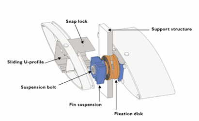
Fixed angle assembly
For the adjustable system, two axles per fin are fitted to the frame.
The fins are fixed to the axles and aligned with a setscrew. The driving
rod is attached and adjusted. Finally the motor is installed and
adjusted to provide the required angle of rotation of the fins.
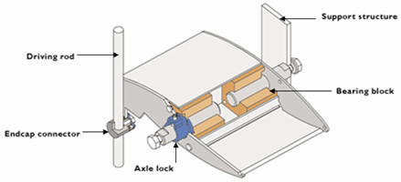
Adjustable angle assembly