![]()
RHEINZINK® - Corrugated Profile
Technology
 |
System Description
|
|||||
 |
||||||
 |
||||||
 |
Surface Quality
Surface Protection
 |
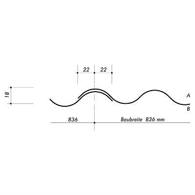
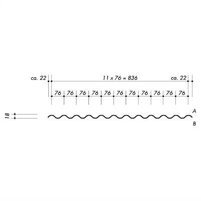
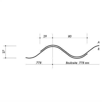
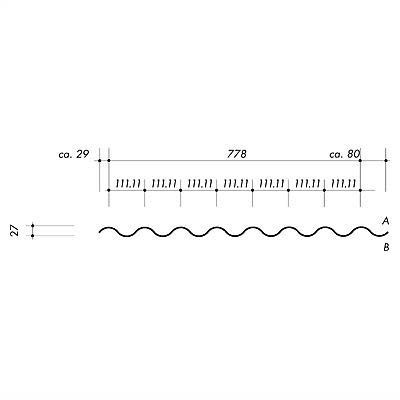
Profile lengths
When fastened directly, thermal expansion of the profiles is compensated by limiting the façade field size to a maximum of 4000 mm and by adjusting the substructure. |
|||||
 |
||||||
 |
Note:
The corrugated profiles can be individually cut-to-size for each project. This is based on a bill of materials completed by the craftsman. An exact measurement onsite is essential nonetheless.Fastening
Fastening is done directly to the substructure by means of self-tapping screws with a sealing washer or rivet. Fastening is visible in the corrugation hollow.
As a substructure we recommend two- or multipart metal bracket systems made of non-corrosive materials. The required distance of the substructure depends on expected wind suction loads, the selected static system (one-, two- or multiple field support), and the fasteners.
The allowable spacing for fixing, can be taken from the measurement tables.
Fasteners
Self-tapping screws are particularly suitable for fastening corrugated profiles to the metal substructure e.g. drill fastener SX 3/4 - L12 - A12 5,5 x L, manufacturers SFS Stadler GmbH. & Co. KG. With its flat, round head and almost invisible sub-head bolt, it fits unobtrusively and harmoniously into the general picture. There is the option of covering these bolts with an ex-works powder coated head,(RAL 7001 similar to blue-grey). Additional details are available from the manufacturer.
Installation is done in one operation using an appropriate insertion tool; no pre-drilling is required.
Choice of bolts is determined by different criteria
Blind rivets (mainly pop cup rivets) are also suitable. The disadvantage is that additional pre-drilling is required.
The use of non-corrosive materials is recommended for application within the façade area. Approval of fasteners should be obtained from building or site supervisors.
Joint Design
![]()
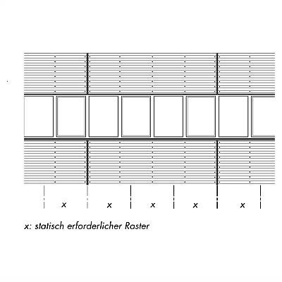
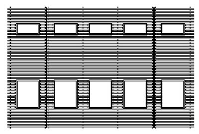
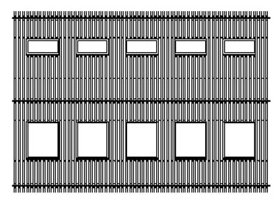
Thermal expansion of the profiles is accommodated by separation - by using expansion pieces. Statically joined fields may not be longer than 4000 mm. The substructure must be formed separately for each field of the façade in the area of the expansion joint.
The corrugated profiles can overlap horizontally. The length of overlap is ≥ 100 mm.
The vertical joint is emphasised with a pilaster strip, e.g. as a sword section. It should be protruding (10 to 15 mm), in order to prevent one from looking into the profile.